A probe can be the ultimate in convenience for doing these kinds of Zeroing operations. Here is a Renishaw probe setting up work offsets:
Renishaw probe setting up work offsets on a VMC…
Each of these tools is similar in purpose, just with increasing capability, automation, and expense. There are a wide variety of other tools available for precisely locating features on your parts and workpieces. Some are more specialized, such as the Blake Coaxial Indicator, which is used to locate bore centers.
You’ll want to have some of these gadgets all fixed up in a tool holder and ready to pop into your spindle for job setups.
For even more examples of how to find Part Zero, see our article which gives 8 ways to do locate Part Zero.
We won’t spend much more time on such things as they’re more properly part of CNC setup and general machinist measuring techniques than g-code programming per se.
Even More Ways to Establish Part Zero
Exercises
1. Take out your CNC machine’s manual and figure out how to zero your CNC machine to establish Work Coordinates. Look up how to read Machine Coordinates versus Work Coordinates on the control panel too.
2. Try some touch offs on your machine. Use the corner of a piece of scrap stuck in a vise for starters until you get good at it.
3. If you have an edge finder, 3D Taster, or probe, give it a try as a way of precisely locating part zero.
4. Decide what your convention for Z = 0 and perhaps Part Zero will be and stick to it.
Chapter 7
Jedi CNC Programming Topics, Techniques, and Resources
You’ve now got most all of the information you need to do basic CNC Programming. You can make the CNC do anything a manual machinist can do on a manual machine.
Congratulations!
But don’t stop now. Next up is perfecting your skills by learning the remaining basic techniques. From there, take on some intermediate and advanced techniques. Don’t worry, CNCCookbook has the articles that will enable you to just keep right on learning, step-by-step.
Basic G-Code Program Structure: Blocks, sequence numbers, words, addresses, and the basic nuts and bolts of g-code line.
Linear Motion: G00 and G01: Moving your CNC in straight lines.
One-Shot G-Codes and Modal G-Codes: Some things in g-code are sticky and others are not.
Circular Arcs: G02 and G03: Moving your CNC along arcs.
Circular Arcs, Part 2: Tips for easier arc programming, arcs in CAM and Simulators, arc troubleshooting, and more.
Tool Length Offsets: Something every CNC machinist should know a lot about.
Tool Data Management: How do you keep up with all your tooling and the compensation information? What about tool presetting?
Basic CNC Lathe Programming: What’s different on a lathe versus a mill? Not too much, but it’s important and this article takes you through it.
Quiz on Basic GCode Programming: Test yourself with a quick quiz on this section. Each question has links to the answers so you can review what you missed.
Intermediate G-Code
Thread Milling: How to thread mill, NPT and tapered threads, When to thread mill instead of tapping
Intermediate Lathe Programming
Lathe Simple Canned Cycles: G90/G92/G94
Lathe Repetitive Roughing Cycles: The Poor Man’s Turning CAM
G71: Rough Turning Cycle: Type I
G70: Finishing Cycle
G72: Rough Facing Cycle
G73: Pattern Repeating Cycle
Lathe Threading Cycles
Gang Tooling for Lathes
Advanced G-Code
Tool Compensation: The Poor Man’s Milling CAM
CNC Macro Programming and Fanuc Macro B: A Mini-Tutorial on G-Code Macro Programming and Fanuc Macro B.
Mirroring the Coordinate System
G-Code Scaffolding: Making CAM Better With G-Code Help
Multiple Part Strategies
G52: Temporary programmable work offsets
Interacting With the Operator
Tweaking CAM Programs: Right Angle Heads and More
Mill 4th Axis Programming
Lathe C-Axis Machining and Live Tooling
Reference Motions
In-Process Probing
Resources
CNCCookbook Blog Posts Relating to GCode Programming: Lots more Tools, Examples, and detailed articles.
G-Wizard Editor: CNC Programming Software for g-coders and a CNC G-Code Simulator. We use it in this course to help teach G-Code.
G-Wizard Calculator: A CNC Machinist’s Calculator
Sample G-Code Files: G-Code examples you can download and play with
CAM Toolpath Strategies: Where plunge roughing, trochoidal machining, and other odd beasts are explained.
3D CAM Toolpaths: Learn the ins and outs of which 3D toolpaths to use in which situations.
Rhino Tips: Some of my tips and techniques for being productive with Rhino 3D.
Like what you read on CNCCookbook?
Join 100,000+ CNC'ers! Get our latest blog posts delivered straight to your email inbox once a week for free. Plus, we’ll give you access to some great CNC reference materials including:
- Our Big List of over 200 CNC Tips and Techniques
- Our Free GCode Programming Basics Course
- And more!
Just enter your name and email address below:
100% Privacy: We will never Spam you!More articles you may like:
CNC allows designers, engineers and hobbyists worldwide to create all kinds of interesting projects. Using CNC tools like milling machines, waterjets and laser cutters, nothing is too far out of reach. With so much to create, you might be wondering how you can go about starting on your next project. How, for example, can you take a JPG and create a wooden sign for your business? It’s simple—all you have to do is convert JPG to G-Code and off you go!
Our latest Scan2CAD guide will take you through the intricacies of converting JPG to G-Code. We’ll cover everything from why you may need to do it, to how the process works, to how Scan2CAD can do it all for you at the click of a few buttons!
- Why is conversion necessary?
- What is vectorization?
- Convert JPG to G-Code
- Tips for converting
General purposes: raster versus vector
JPG is a raster file format which is used predominantly for digital photography. While it’s a common file format (and small in size, which makes it ideal for sharing) it comes with a range of issues that all raster file types suffer from. Rasters are made up entirely of pixels—those tiny squares that become more noticeable when you zoom in or enlarge your JPG. Unfortunately, this means that changing your raster’s scale is difficult and ill-advised. They’re resolution dependent, after all!
Free G Code Images Download
In comparison, vector file types like DXF and DWG are mathematically perfect. Used in graphic design, engineering and CAD, vectors don’t lose their quality. Unlike rasters, they’re made up of paths, not pixels. This means that it doesn’t matter how much you zoom in or change the scale: they remain high in quality. As such, you could take the same vector image and use it on both a business card and a billboard.
For CNC: from JPG to G-Code
CNC machines like routers or milling machines make use of a series of pre-programmed commands to—in subtractive processes—take material from your piece. The most popular programming language is G-Code, the creation of which marked an important step in the history of CAM. This language controls exactly how your CNC machine’s tools move. From how fast your tools move to the speed of rotation, everything is covered in the G-Code.
You can see why, then, you can’t simply take a JPG and automatically use it with your CNC machine. These machines only work with vector file formats or G-Code. Fortunately, conversion software like Scan2CAD can trace your simple JPG and convert it to a vector file format so you can take your design to fabrication. This vector can then be converted directly to G-Code which can be read by control software and used to run your CNC machine.
Conversion—or vectorization—involves taking your raster, in this case a JPG, and converting it to a vector. This can be done by either manual tracing or automatically tracing your JPG. We’ll discuss how each process works briefly and help you decide which is best for you.
Manual tracing
If the name didn’t give you a clue, manual tracing involves tracing—or drawing—over your raster image with vector lines. This can be done with software like Inkscape and Illustrator. If the idea of using your mouse to click and trace over your entire image exhausts you, you might instead opt to use a tablet and graphics pen.
Automatic tracing
As you might have guessed, automatic tracing involves using software—like Scan2CAD—to instantly convert your JPG, for example, to a vector and then G-Code. The way Scan2CAD works is by detecting the lines present in your raster and converting them to vector entities. This can then be converted to G-Code ready for use with your CNC machine.
Which process is better?
One of the main factors to take into consideration is time. Manual tracing is a time-consuming and taxing process. If you’re pressed for time—or you’re anything like us and you’re rushing to start those CNC projects—you might be looking to get your JPG converted ASAP! In this case, automatic tracing is the process to pick. On the other hand, if you’re working with a more complex image, manual tracing might be the better option. Some conversion software can struggle with understanding and recognizing certain raster images.
If you’re still unsure, make up your mind by looking at tracing: manual or automatic.
Avoid online converters
You might think that the easiest thing to do is to search for “convert JPG to G-Code” into your browser and choosing the first result. Unfortunately, as we frequently warn our readers, online converters are extremely temperamental. Some of the many disadvantages include:
- Limited capabilities in converting certain entities
- No conversion for large file sizes
- No batch conversion
- An output that, more often than not, won’t work with CAM
- Problems with converting raster text to vector text
That’s not even mentioning the most obvious disadvantage—the possibility of accidentally downloading a dangerous virus or trojan. In all, you have to ask yourself: is facing the pitfalls of online converters really worth it? If your answer is no—as we hope it is—we can show you how Scan2CAD can convert JPG to G-Code in a few simple steps!
Using Scan2CAD to convert JPG to G-Code
We don’t call Scan2CAD the market-leading raster-to-vector converter for no reason! While its primary focus is the conversion of raster technical drawings to vector images, Scan2CAD can also be used as a vital part of the CNC process. The many ways Scan2CAD has been used include routed signs, metal sculpting and glass reproduction.
Unlike online converters, Scan2CAD makes use of vectorization type settings to give all users a specialized conversion suited to the type of image they’re converting. If you’re converting a JPG for use in CNC, for example, you’d select the “CNC Profile” setting. Scan2CAD, using pre-programmed variables, would then try to reduce the number of lines and node points in your image. Why? The cut paths of your CNC machine relate directly to the number of vector shapes you have. Reducing them, therefore, makes it easier for your machine.
The best part about the entire vectorization process in Scan2CAD is that it takes mere seconds to complete. Once the process is done, you can then skip the entire CAM process and convert your image directly to G-Code!
In this animation we convert an anchor image to a vector outline for CNC using Scan2CAD
How it works
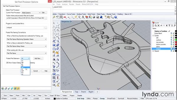
All you’ve got to do is load your JPG in Scan2CAD and click on one of the vectorization options. Then, just a few seconds later, you’ll have converted your raster image to a vector. You can then choose to save your new image in a G-Code format. Of the popular CNC formats, Scan2CAD supports .NC, .CNC and .TAP.
Now you can convert any JPG—or other raster file type—to one of these three G-Code file types. Scan2CAD’s CNC Export option gives users a selection of options:
- G-Code Bezier Options: cubic splines, arcs or polylines
- Arc and Circle Rotation: clockwise or anti-clockwise
- Z Settings: Z offset, Z max for passes, Z limit per pass and Z retract per pass
- Scale Settings: setting the required scale, e.g., inches or millimeters.
What not to convert
To get the best possible output, you should only look to convert high-quality rasters. Otherwise, you’ll run into issues when converting. For example, if your image is low-quality, Scan2CAD will struggle to detect the lines and curves present. Fortunately, we’ve got some top tips to help you pick the right image…
- Only pick images with high resolution. If it’s pixelated, you should look for an alternative.
- Try for a better raster file format. JPGs aren’t the best file format—you might look towards using a TIFF instead, taking advantage of its lossless compression.
- Less is more. Try to use images with as few colors as possible. For CNC in particular, 2-bit color is a necessity.
- Clean, clean, clean. Avoid images that have blurred areas, shadows or any overlap—it will only cause issues during vectorization.
- Avoid compound curves. CNC machines aren’t big fans of curves (splines, ellipses), and instead prefer polylines which only include line and arc segments.
You can see more common problems associated with raster images in the image below…
Pre-conversion tips
It’s worth noting that sometimes, even after following the tips highlighted above, there’s no avoiding images that are somewhat flawed. Fortunately, Scan2CAD doesn’t just support you through vectorization—it also comes with market-leading tools that enable you to clean up your image before and after conversion. Here are a few examples of top raster effects…
- Thresholding is key. By using Scan2CAD’s thresholding tool, you can reduce the colors in your image to just black and white, making it easier for the software to detect the entities in your raster. You can choose between simple and adaptive—the latter of which enables you to define the point at which pixels are classed as “black” or “white”.
- Remove speckles and holes. You can easily remove stray pixels with the despeckle tool which allows you to erase pixels that are larger than a certain amount. Just as easily as you can get rid of speckles, you can also fill in any holes to make solid objects.
- Thicken lines. If you’re looking to convert JPG to G-Code, you need an image without gaps or broken lines. The thicken lines tool makes this a problem of the past. Be sure to look over your image carefully, however: you don’t want to accidentally join lines that are meant to be separate.
- Smooth image. If your image has too many “hairs” around the edges, you can use the smooth tool to—yes, you guessed it—smooth out the edges. This will stop the software from drawing vectors around these hairs.
Post-conversion tips
The last thing you want is to take your G-Code to your CNC machine only to find that you’ve missed a few issues—this could lead to you wasting time and resources on a ruined output. As such, it’s incredibly important that you check your vector closely before you save it as G-Code and send it to your control software.
You should check that your vector output only contains single line cut paths and that these lines are all connected—one coherent cut path is needed. This is particularly important around the corners and curves of your image. Using Scan2CAD, you should try to remove as many node counts and intersections as possible. You might also consider converting any broken entities (like arcs or Beziers) to polylines.
And that’s all there is to it! Now you’ve successfully managed to convert JPG to G-Code, the possibilities are practically endless—you’ll be able to start a multitude of CNC projects. Got a logo you need to mill? Vectorize your logo quickly and efficiently with Scan2CAD!
Whether you’re a professional or hobbyist machinist, there’s always something new to learn or enjoy in the realm of CNC. Scan2CAD loves to help, which is why we’ve compiled all of our top resources…
Software and hardware
If you’re not sure what control software to use, or you’re in the market for a new CNC kit—you’ve come to the right place. Get all the best tips and tricks for CNC software and hardware in Scan2CAD’s CNC-related articles:
Free DXFs
Sometimes we just want to get straight out there and start a new CNC project. If you’d rather skip the fuss of finding the perfect raster image to convert to vector and then G-Code, why not use ready-to-cut DXFs? Simply use one of these 13 sites with free DXFs and export them directly to G-Code using Scan2CAD. Or, you can receive free DXF packs from Scan2CAD when you sign up using your email.
Scan2CAD
If you want to convert JPG to G-Code or any design for CNC, Scan2CAD should be your first port of call. A professional, market-leading converter, Scan2CAD comes with a range of top tools that enable you to convert from a number of file types to vector or G-Code file types. Got raster text in your image? With Smart OCR, you can train the software to recognize even handwritten text! And with features like batch conversion, you can convert hundreds of files in no time at all.
With no obligations or limitations, you can enjoy the full range of Scan2CAD features with our free, 14-day trial. Simply click on the link below to download now.


